Electronics
Now, that the body is ready, it is time to equip it with the electronics. At this point, a lot of soldering will come up, so be aware and have some time on your hands. It is also recommended to word properly to avoid and shorts or to break any components.
Installing the LEDs
In a fist step, it is time to install the LEDs on the base plate.
Remove the baseplate from the frame again and put the frame aside.
From the WS2812B RGBW LED strip, cut of 11 sections of 10 LEDs each.
Glue the LED strips to the engraved positions on the base plate.
Important
Pay attention to have the data in and data out directions aligned properly. Take the LED index numbers as help to align data in and data out properly. You should end up with alternating directions for the LED strips.
Cut of another four individual LEDs.
Glue the 4 individual LEDs on the engraved marks in the corners.
Also pay attention here, to have data in and data out aligned with the index numbers.
The image below shows the base plate after installation of the LEDs.
Wire up the ground (GND) terminal to the LEDs
Use black wire with 0.5 mm2 cross section
On the top side, make hops from one strip to the next to supply the GND line to every strip
Make sure to leave about 50 cm of spare wire at the first LED.
From one of the top corners (index 4, or 104), connect to the nearest corner (index 3, or 2), then cross over to the other top corner.
Similarly connect the bottom corners (index 0, or 1) to the bottom corners of the grid (index 13 or 113).
Wire up the +5 V line to the LEDs
Use red wire with 0.5 mm2 cross section
Distribute the power in a similar manner as the GND line, just along the bottom of the grid.
Again make sure to have about 50 cm spare wire at the first injection point.
In an equal manner, wire up the corner LEDs.
Note
In the image below, +5 V (top, red) and GND (black, bottom) are inverted to these instructions. Following the instructions leads to the data line always being on the inside of a GND or +5 V wire loop.
Solder in the data line.
Use blue signaling wire to distribute the data.
Start from the highest index and follow the data line in inverse order. Everywhere, where there is a connection needed connect to the next lowest index.
You should end up with alternating loops on the top or bottom of the grid.
Connect the corners in the same manner.
Make sure to have approx. 50 cm spare signal wire at the data in (DIN) terminal of the LED with index 0.
Use some electrical tape to fixture the loose wire bundles going around the outside of the base plate.
To finish up, reinstall the baseplate in the frame. Carefully feed all wires through the wire feed through cutouts in the corner blocks and vertical and horizontal long pieces.
The image below shows the wired up LEDs. Note, that positions of GND (black, bottom) and power (red, top) are inverted with respect to these instructions.


Installing controls and logic board
If not done already, cut openings into the edge band, where there are cutouts for buttons, power switch, barrel socket and photodiode in the frame.
Prepare the barrel socket, power switch, barell socket and photodiode with wires of suitable length like in the image below.
Use at least 0.5 mm2 wire for +5 V and GND lines.
For buttons and photodiode as well as for power supply to the logic board (not the LEDs) 0.14 mm2 signal wire suffices.
Note, that the image shows crimped connections in various points, however soldered connections work just as well.
Install the barrel socket in the bottom of the frame.
Install the power switch and the three buttons on the right side of the frame.
Install the photodiode in the top of the frame.
Install the logic board with 4 M2x8 mm standoffs and 8 matching washers and M2x5 machine screws. Note, that you can run the wires for the buttons underneath the logic board.
Connect photodiode and buttons to the top connectors of the logic board.
Connect the barrel plug to the power switch. From there run each one ground and +5 V connection to a 3 power wago clamp.
Connect the GND and +5 V lines from the LEDs to the same Wago clamps.
Connect three wires to the GND, DOUT, and +5 V connectors at the bottom of the logic board.
Attach the GND and +5 V wires to the Wago clamps from before.
Finally, use a 2 port Wago clamp to wire out DOUT of the logic board to the data line of the LEDs.

Prepared wires and components for power (top left), control buttons (top right), control board supply (bottom left), and photodiode. |

A closer look at the logic board with connections for buttons and photodiode at the top and GND, DOUT, and +5 V at the bottom. |
If everything went right, you are now ready for a first function test. Load up a suitable test script to the logic board and supply power to the OpenWordClock. Hopefully, you see some LEDs lighting up. The image below gives you an overview over a fully wired up OpenWordClock.
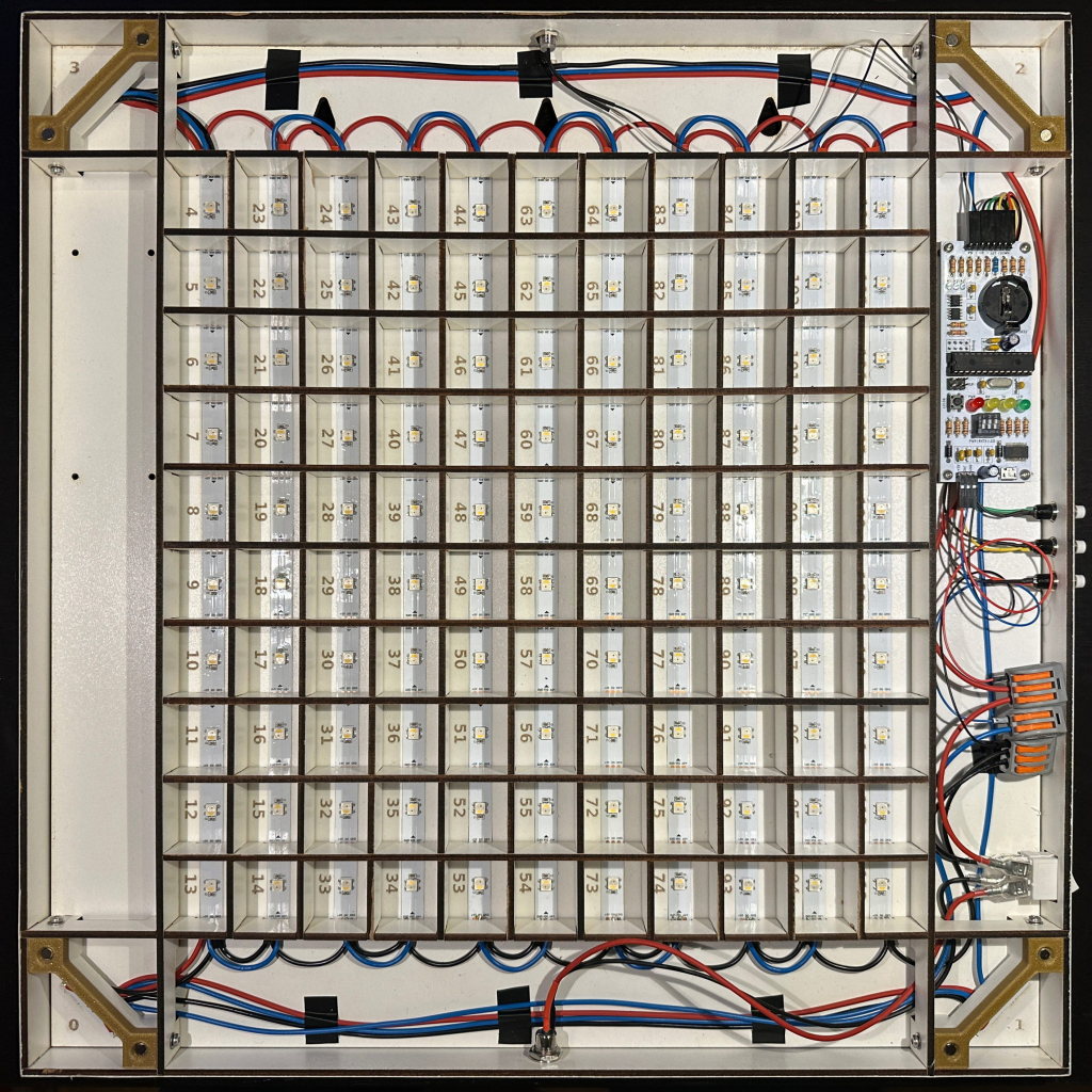
Internals of an OpenWordClock with all connections made.